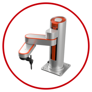
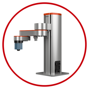
Stepping Series Actuator – Z-Mod-ST-59B Electric Actuator

Main Category
Intelligent Electric Actuator /Smart Electric Actuator / Electric Actuator /Intelligent Actuator
Unique collaborative features
- Higher placement accuracy can be achieved by adjusting parts and aligning them, making the operation more reliable.
- Torque/motion modes can be performed simultaneously without resetting.
- The push mode can detect the pushed object height, making Z-Mod's performance even more intelligent.
Features

Highly integrated system
Innovative design that eliminates the need for sensors, while integrating the motor.
Controller within the module for optimal use of space and stroke.
Easy-to-use software
No need to build a motion platform, as Z-Arm series control software enables user-friendly operation.
The simplified programming environment allows even inexperienced users to work collaboratively.
Simplified but not simple
Servo series: no external sensors required
Cost-effective
Z-Mod offers industrial-grade performance at an affordable price, with more personalized services.
Built-in controller (screw series), external controller (belt series)
Accurate installation reference surface
Zero backlash nut (T-type screw) / imported steel wire polyurethane synchronous belt with clean cloth (synchronous belt series)
The ultimate stroke-to-total length ratio is shorter for the same effective stroke
More suitable for small loads, high speed, and limited space occasions
Relatively good sealing, screw and synchronous belt are not directly exposed
Related Products

Specification Parameter

| Stepper motor specifications | HL57CM23(Reference to Leistritz 57CM23) | |
| Rated torque | Reference Curve Performance Chart | |
| Ball screw lead |
54mm |
|
| Maximum speed | Horizontal:370mm/s(1.5kg Payload) | Vertical:300mm/s(1.5kg Payload) |
| Rated acceleration (Note 1) |
/ |
|
| Maximum payload capacity horizontal/wall-mounted |
6kg |
|
| Vertical Mount |
4kg |
|
| Rated thrust |
100N(Horizontal) |
|
| Stroke range | 100~800mm(100mm Interval) | |
| Motor rated speed | Reference Curve Performance Chart | |
Note 1: 1G=9800mm/sec² The maximum speed is only for reference. The load and speed are inversely proportional.
| Repeatability | ±0.03mm |
| Driving mode | Timing belt (imported steel wire polyurethane) |
| Dynamic allowable torque (Note 2) | Ma:100N·m;Mb:100N·m;Mc:130N·m |
| Load allowed extension length | 200mm |
| Sensor | / |
| Sensor cable length | 1.5m |
| Base material | Extruded aluminum profile, black gloss |
| Installation plane accuracy requirement | Flatness below 0.05mm |
| Working environment | 0~40℃,85%RH(Non-condensing) |
Note 2: Value at 10,000km working life
Sensor wiring diagram

Torque Definition

Dimensional diagram code explanation · quality Unit:mm
|
Effective payload |
100 |
200 |
300 |
400 |
500 |
600 |
700 |
800 |
|
A |
280 |
380 |
480 |
580 |
680 |
780 |
880 |
980 |
|
C |
100 |
200 |
300 |
400 |
500 |
600 |
700 |
800 |
|
M |
2 |
4 |
5 |
7 |
8 |
10 |
11 |
13 |
|
N |
6 |
10 |
12 |
16 |
18 |
22 |
24 |
28 |
|
Quality (kg) |
2.4 |
2.76 |
3.12 |
3.48 |
3.84 |
4.2 |
4.56 |
4.92 |
Our Business